Brocade Communications Systems 6510 Installation Guide Page 31
- Page / 66
- Table of contents
- BOOKMARKS
- Brocade 6510 1
- Contents 3
- Document conventions 5
- Notes, cautions, and warnings 6
- Brocade resources 7
- Document feedback 8
- About This Document 9
- What’s new in this document 10
- Brocade 6510 Introduction 11
- Platform components 12
- Facility requirements 13
- Port side of the Brocade 6510 14
- 53-1002174-10 15
- Installation precautions 17
- Power precautions 18
- ESD precautions 18
- RTC battery 19
- Environmental considerations 19
- Brocade 6510 configuration 21
- Creating a serial connection 22
- Switch IP address 22
- Date and time settings 23
- Local time synchronization 24
- Setting the date 24
- Setting time zones 25
- Enabling Access Gateway mode 27
- Disabling Access Gateway mode 28
- Brocade 6510 Operation 29
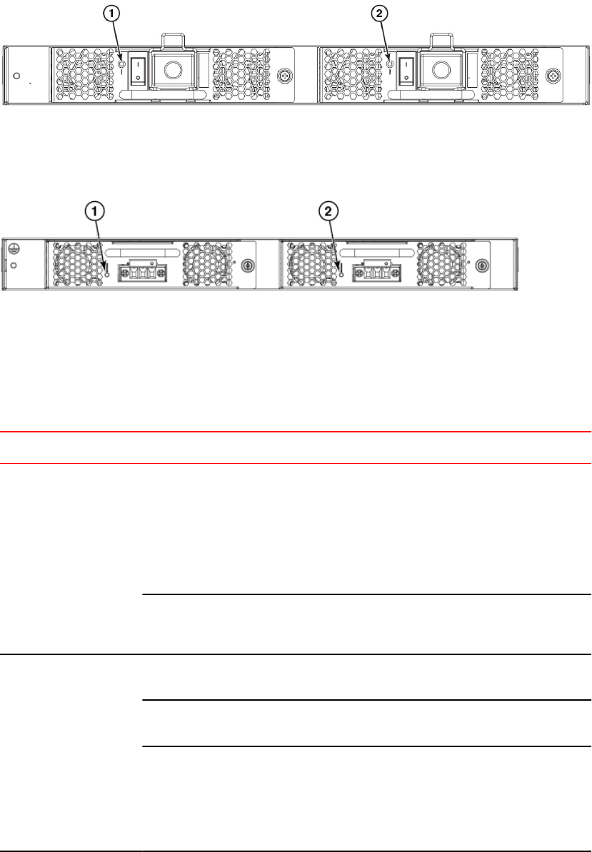
- LED locations 30
- LED patterns 31
- POST and boot specifications 33
- Interpreting POST results 34
- Brocade 6510 Maintenance 34
- Diagnostic tests 36
- Brocade 6510 Management 37
- Introduction 41
- Time Required 45
- Items Required 45
- System specifications 49
- Fibre Channel 49
- Ethernet 50
- Environmental requirements 51
- Memory specifications 55
- Regulatory compliance (EMC) 56
- Regulatory Statements 57
- China CC statement 58
- China ROHS 59
- FCC warning (US only) 59
- VCCI statement 59
- Caution and Danger Notices 61
- Electrical cautions 62
- Danger Notices 64
Related products and manuals for Network switches Brocade Communications Systems 6510
 (23 pages)
© 2020, manymanuals.com. All rights reserved. | 1.081 s |
 Manymanuals.com
 Manymanuals.de
 Manymanuals.fr
 Manymanuals.it
 Manymanuals.pl
 Manymanuals.cz
 Manymanuals.es
 Manymanuals-pt.com
Comments to this Manuals